4.3.1.16. NXdisk_chopper
Status:
base class, extends NXobject
Description:
A device blocking the beam in a temporal periodic pattern.
A disk which blocks the beam but has one or more slits to periodically let neutrons through as the disk rotates. Often used in pairs, one NXdisk_chopper should be defined for each disk.
The rotation of the disk is commonly monitored by recording a timestamp for each full rotation of disk, by having a sensor in the stationary disk housing sensing when it is aligned with a feature (such as a magnet) on the disk. We refer to this below as the “top-dead-center signal”.
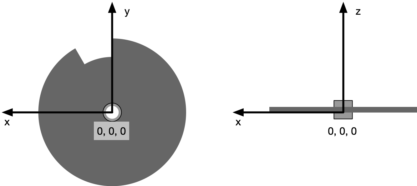
Angles and positive rotation speeds are measured in an anticlockwise direction when facing away from the source.
Symbols:
This symbol will be used below to coordinate datasets with the same shape.
n: Number of slits in the disk
- Groups cited:
Structure:
@default: (optional) NX_CHAR
Declares which child group contains a path leading to a NXdata group.
It is recommended (as of NIAC2014) to use this attribute to help define the path to the default dataset to be plotted. See https://www.nexusformat.org/2014_How_to_find_default_data.html for a summary of the discussion.
type: (optional) NX_CHAR
Type of the disk-chopper: only one from the enumerated list (match text exactly)
Any of these values:
Chopper type single
contra_rotating_pair
synchro_pairrotation_speed: (optional) NX_FLOAT {units=NX_FREQUENCY}
Chopper rotation speed. Positive for anticlockwise rotation when facing away from the source, negative otherwise.
slits: (optional) NX_INT
Number of slits
slit_angle: (optional) NX_FLOAT {units=NX_ANGLE}
Angular opening
pair_separation: (optional) NX_FLOAT {units=NX_LENGTH}
Disk spacing in direction of beam
slit_edges: (optional) NX_FLOAT (Rank: 1, Dimensions: [2n]) {units=NX_ANGLE}
Angle of each edge of every slit from the position of the top-dead-center timestamp sensor, anticlockwise when facing away from the source. The first edge must be the opening edge of a slit, thus the last edge may have an angle greater than 360 degrees.
top_dead_center: (optional) NX_NUMBER {units=NX_TIME}
Timestamps of the top-dead-center signal. The times are relative to the “start” attribute and in the units specified in the “units” attribute. Please note that absolute timestamps under unix are relative to
1970-01-01T00:00:00.0Z.@start: (optional) NX_DATE_TIME
beam_position: (optional) NX_FLOAT {units=NX_ANGLE}
Angular separation of the center of the beam and the top-dead-center timestamp sensor, anticlockwise when facing away from the source.
radius: (optional) NX_FLOAT {units=NX_LENGTH}
Radius of the disk
slit_height: (optional) NX_FLOAT {units=NX_LENGTH}
Total slit height
phase: (optional) NX_FLOAT {units=NX_ANGLE}
Chopper phase angle
delay: (optional) NX_NUMBER {units=NX_TIME}
Time difference between timing system t0 and chopper driving clock signal
ratio: (optional) NX_INT
Pulse reduction factor of this chopper in relation to other choppers/fastest pulse in the instrument
distance: (optional) NX_FLOAT {units=NX_LENGTH}
Effective distance to the origin. Note, it is recommended to use NXtransformations instead.
wavelength_range: (optional) NX_FLOAT (Rank: 1, Dimensions: [2]) {units=NX_WAVELENGTH}
Low and high values of wavelength range transmitted
depends_on: (optional) NX_CHAR
NeXus positions components by applying a set of translations and rotations to apply to the component starting from 0, 0, 0. The order of these operations is critical and forms what NeXus calls a dependency chain. The depends_on field defines the path to the top most operation of the dependency chain or the string “.” if located in the origin. Usually these operations are stored in a NXtransformations group. But NeXus allows them to be stored anywhere.
The reference plane of the disk chopper includes the surface of the spinning disk which faces the source. The reference point in the x and y axis is the point on this surface which is the centre of the axle which the disk is spinning around. The reference plane is orthogonal to the z axis and its position is the reference point on that axis.
Note: This reference point in almost all practical cases is not where the beam passes though.

GEOMETRY: (optional) NXgeometry
DEPRECATED: Use the field depends_on and NXtransformations to position the chopper and NXoff_geometry to describe its shape instead
OFF_GEOMETRY: (optional) NXoff_geometry
This group describes the shape of the beam line component
TRANSFORMATIONS: (optional) NXtransformations
This is the group recommended for holding the chain of translation and rotation operations necessary to position the component within the instrument. The dependency chain may however traverse similar groups in other component groups.
Hypertext Anchors
List of hypertext anchors for all groups, fields, attributes, and links defined in this class.